Tuesday, August 13, 2013

Low cost GPS watch with data download

I have been using Runkeeper to track my exercising for some time. It is a nice program that utilizes the GPS of the smart phone to record speed, distance, etc. of a run, and it is quite flexible. I did run into some small problem lately. I have been switching to a Samsung Galaxy phone. The phone is a bit dated, and I found that GPS of it does not work very well. A bit search revealed that Samsung phones (particularly the one I am using) has relatively bad GPS design. With Runkeeper, it does not track very well, and gives me constant wrong readings. So I am out looking for GPS watches.

My criteria for a GPS watch is pretty simple. I need it to track distance and speed. I like it to have a way to download GPS track off the watch so I can manually upload it to Runkeeper (in this way to keep my record all in one place). And I like to achieve that with the lowest option as possible.

Most of the GPS watches are pretty expensive. There are only a handful of low cost GPS watch in the market in the range of around $100. While I am doing my research, a review by a guy who called himself DC Rainmaker caught my attention. The watch in review is Timex Marathon. Timex Marathon is one of the cheapest watch in the market, but interestingly is the first one that is made water proof. What is interesting about this watch is that even though it does not come with data download in the package, the reviewer has connected a data cable from Soleus (another low cost GPS watch maker) to Timex Marathon and the data download did work through it. What is more fun than having an easy hack to get the feature I wanted and at the same time save money!

So I promptly ordered a (used) Timex Marathon from a seller on Amazon at $50. It comes with a two-prone cable. I opened the back. Sure enough, there are four contacts made on the PCB board. That seems to be a perfect match to the four USB wire pin-outs. Out comes my soldering iron. Twenty minutes later, the cable is mod, and I have it connected to my computer. But ... my computer did not recognize the USB device! Back to the review page with more reading, and I started to read the comments. It turns out that I am not the first guy who tried the cheap mod. And it appears that it did not work that way.

A bit search of the installation directories of Soleus software found that it has a device driver folder for USBXpress. This is for Silicon Labs' USB serial chip. Could it be that it uses a serial port to talk to the watch? This makes sense as it is not necessary to put USB circuitry in the watch if it does not always need it. But a few attempts seems to indicate that the Soleus software is looking for some specific devices rather than a common serial port.

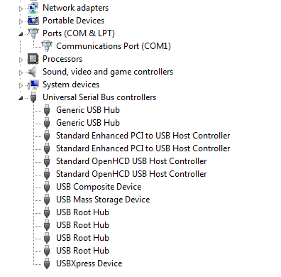
The proper four-prone cable is needed. After a few tries, I went ahead and ordered the data cable from Soleus for $29. It came in in a few days and when connect it up, the data download works. The cable itself is not just a simple cable, but has a Silicon Labs CP2012 chip inside. When connected to the computer, it appears as "USBXpress Device" instead of a serial port. Below is how it looks like in my device manager.


After much ado, I was able to do what I wanted with $80. The next working solution will cost $50 more. Soleus Fit watch costs $100, but needs additional $30 for the download cable. Soleus GPS 2.0 (which is identical to Timex Marathon, and is now water proof), has a $150 MSRP but is on sale at $130. This is not as good a saving as I originally anticipated, but it is not too bad. And I got some fun trying these.


Tuesday, July 30, 2013

3D Printer Extruder Design (Part 2) - K-Head

As discussed before, the key to extruder design is in the thermo control. As I was trying to get the QU-BD extruder to work, I have kept on making improvements and changes to it. By the time I had finally had it working reliably, it is already a complete different design.

Here are some picture of the QU-BD extruder and how they look on my printer. It is actually behind a wood block that holds it on the default tool holder that comes with the ShapeOko CNC, so it is not clearly visible.


Here is the final working extruder on my printer. For the fun of it, I would call it K-head. It is held by an aluminum holder. Also, more details can be seen with the fan off on the second picture.


Here are a few most important improvements I have made to it:

1. The hot-end tube


The original hot-end of QU-BD uses a stainless steel tube. This is actually one of their selling point: a complete metal extruder. However, I find out that even though stainless steel has pretty low thermo conductivity, that is still way to much for a hot-end. Indeed, the majority of the filament jam is caused by too much heat is going up the hot-end tube. I have tried to put extra heat sinks on the tube, has drill out the inside to a larger size, and tried to print at high speed trying to get cooler filament into the melting portion. None works until I changed the hot-end tube to a different material.

The tube you see here in the final working K head is made of PEEK. Indeed, it is called "Self-lubricating Carbon-Filled PEEK" (1/4" D, 1 ft, 1595A11, for under $8.75). Because I don't own a lathe, I like it very much the factor that PEEK is much easier to drill and tap than stainless steel.

With the new PEEK tube, I can touch the aluminum holding plate and only feel warmth even when the hot-end is heated to and held at 210C for a long time. The PEEK tube not only have a low thermo conductivity, it is also self-lubricating which makes jamming very unlikely.

2. Thermo shield of the heating block

This is with the original QU-BD but it is not shown in their instructions. It took me a long time to realize what the white piece is for (it is a ceramic heat shield tape). And doing that greatly cuts down heat radiation loss, and makes the hot-end heating and temperature much more stable.

3. Aluminum filament tensioner

The original QU-BD uses a HDPE block with a set screw to hold the filament to the driving wheel. I found that hardly working. Maybe I am too cheap, and the filament I bought (from Amazon) has poor uniformity of diameter. There are a lot of designs on the Thingiverse on the tensioner for direct drive cold-ends, but it takes a working printer to print them. Even when I finally to get my printer work just enough to print a piece with PLA, I found out that it did not hold well as the motor is getting hot from driving current. So I finally just decided to make it in aluminum so it works under any temperature.

A small trick also used here which I learnt from one of the Thingiverse designs. The trick is to use binder clip instead of steel springs to supply the tension. Not only the binder clip is easily strong enough, it can also be held in place very easily by drilling small holes in the holder. The binder clips are very easy to find, which is another advantage too.

So here is the K-head that is finally working reliably for me. Through the process, I had a lot first hand experience about the extruders, particularly what works and what does not. The QU-BD extruder is really not a good design. It is not that theirs is not working. It might be, but with that design, there is a very narrow band of setting that it might work (specific filament, specific stepper motor, specific temperature, specific print speed, etc.) But real world reality is never always in the ideal case, and anything different will throw off the balance. In that sense, we can clearly see that the QU-BD is not a good extruder design.

My K-Head is a lot more reliable, and works in a wide range of settings. I will see if I can keep on making it better. For now, I will go print some fun stuff.

Friday, July 26, 2013

3D Printer Extruder Design (Part 1)

The extruder is the core of a 3D printer, because besides the extruder all that is left of 3D printer is a Cartesian Robot (i.e., some machine that moves in X/Y/Z space).

In the process of building my 3D printer, I found out that most of the time is spent trying to get the extruder to work (maybe that is because I have the Cartesion robot part working already from the hobby CNC). I started with a QU-BD extruder kit and thought it should be a straight forward process. But it is anything but. In the process of getting it to work, I have been replacing this and that of the extruder. And the end result is something that is completely different and new.

Below is a picture of QU-BD extruder. It looks nice, but as discussed below per my experience, is not a good extruder design.


The key issue of designing a good working extruder is thermo control, i.e., to control the heat. The basic of extruder is very simple. There are two parts: a cold-end and a hot-end. The cold-end is the stepper motor and corresponding mechanics that drives the filament. The hot-end is basically a tube, with filament coming in on one side, molten plastic going out on the other. The side on which the molten plastic goes out is fitted with a nozzle, so the plastic is squeeze to form the printed parts. But how to squeeze the molten plastic out? It is driven by pushing on the incoming filament by the cold-end.

Below is a diagram for the hot-end of J-Head, a popular extruder used in many 3D printers.


Because the tube is heated, so the incoming filament is getting heated while it is going down from top. As it is heated, it gets soften and also expand in size. Eventually, the filament is melt into molten plastic to be squeezed out. In physics and material science, this is called Glass Transition. Here lies the key of the extruder thermo design. If the filament is getting close to the glass transition too high on the tube, pushing on the filament will expand on the soften filament and push outward toward the wall of the tube. This creates a plug and prevented the force from doing downward to squeeze the molten plastic out. Thus created a jam.

To avoid these jam from happening, there are a few factors in play:

  1. Extruder temperature. Hotter set temperature would make the tube hotter, but it also makes molten plastic easier to be squeezed out.
  2. Thermo conductivity of the tube. More conductive material makes more section of the tube hotter.
  3. Feeding speed. Fast feeding can make filament going through the tube cooler.
  4. Heat shield and insulation. Radiation of the heat also plays an important role in thermo control.
  5. Other heat sources. The stepper motor can get really hot when run at high current.
  6. Cooling. Active cooling with a blowing fan.

A working extruder will find one of such point of above combinations for the extrusion to work continuously. However, a well designed extruder will have a wider range of combination and conditions for it to work well. In my experience, QU-BD extruder emphasizes too much on the all metal and turned out not be a good design. I will discuss in my next post what would be a better design of an extruder.


Wednesday, July 3, 2013

Converting CNC to a 3D Printer

I have finally got time to convert my CNC into a 3D Printer.

The process looks relatively simple on the paper: just replace the cutting tool head with an extruder, and optionally add a heated print bed. The extruder is the part that extrudes melted plastic to form the printed object. The heated bed is needed to eliminate warping of the printed object. Without the heated bed, the bottom layers would already be cooled when the top layers are printed, resulting in warping and lifting of corners away from the bed.

First there is a picture of the completed conversion, and a few printed object in the foreground. The extruder is behind the wooden block which holds it in place. The heated bed is the red piece on the bottom, and on top of it is a aluminum sheet with blue painters tape.


In reality, it is a great learning process, and it is not at all easy. This is my first printer, so I have a lot to learn about the extruder (which is the most critical part of a 3D printer). To get it to extrude smoothly is a huge battle, because I have no experience on where to look when things do not work (and it still does not work till today). But after a long struggle, and a lot of trial and error, I can say that I have a much better idea on the issues of 3D printer now, and how to solve them. I will talk about them in the next few days when I am still waiting for some parts to arrive in mail.

Here are a useful link about 3D printing.

On their website, they said that this is a "first general-purpose self-replicating manufacturing machine". I disagree with that statement. The machine only prints the plastic parts of the frame. It does not make any of the metal rods, the nuts, the bearing, let alone the electronics. That statement of "self-replicating" is a marketing gimmick. However, aside from that, there are tons of useful information on it, and a lot of smart people are contributing. If you need a place to learn about the in and outs of 3D printing, that is the best place to start.

Sunday, February 17, 2013

Building a ShapeOko CNC

After some study, I have decided to build a ShapeOko CNC. I got the ShapeOko mechanical kit from Inventable.

The kit comes with all the machined parts in a box. The first thing I did was an inventory count, and everything comes out right. Here is the picture of the parts in the box.


The building process is quite straight forward and easy. The online wiki instruction is very helpful with updated info that corrects the errors in earlier version. The user submitted notes are especially useful. Here are the assembled Y-Axis Idle and Motor plates.

Here are the assembled X-Axis Motor and Z-Axis plates.


The assemble gets a bit more involved later when the plan calls for tapping a few holes on the frame. I have to go out to buy a tap/die set. Things do go smoothly most of the way.

The other complexity is with the electronics that runs the CNC. I have only the mechanical kits, so I bought the motors separately. Because I was intending to do 3D printer eventually, so I got an Arduino board and an RAMPS to control the motors. There is really a lot of overlapping between the CNC and 3D printer control. The emerging of the 3D printer community has really advanced the electronics and the software needed to run these 3D robot machines. I will write a separate post on it. For now, here is the completed CNC. I added my own base board and sacrifice board hold downs.


And here is one of first cut I made with this CNC - just leveling a square. I mounted a Dremel tool as my cutting spindle. You can see from the cut that it is not perfectly aligned. There is still a lot of work to do for improvement. For now, I have my first CNC and it is working!


Update: This unit is assigned a ShapeOko serial number 1,302.

Monday, January 28, 2013

Linear drive: Belt/Pulley or Leadscrews

There are two common low-cost ways to drive linear motion: Belt/Pulley or Leadscrews. It seems obvious that belt/pulley can run faster, while leadscrews can take a larger load. But if the machine needs to do any 3D printing, the belt and pulley is the only choice.

The reason is simple: leadscrews do not go fast enough. Take, for example, a common cheap 1/4" x 20 threaded rod on a common NEMA 17 stepper motor. The motor turns at around 300 rpm. At that rate, the drive is moving 15 inches per minute, or 6 mm/s. That's painfully slow, as a decent 3D printers now-a-day can run about ten times as fast. Of course leadscrews can go faster with a multi-start ACME rod. But that drives the cost up quite a bit, and is no longer options in the low cost world.

As a result, all of the 3D printer or 3D printer / CNC combo design I see uses belt/pulley to drive the X/Y motion.


Does it make sense to combine 3D printer and CNC?

The question is: Does it make sense to build a combined 3D printer and CNC? It seems that despite the similarities in 3D printer and CNC, there are a few important differences.

A CNC needs to withhold a lot of lateral force from the mill head, so the mechanical structure needs to be build rigid and solid. That means any CNC machines are probably a bit heavy. On the other hand, a 3D printer only needs to move a relatively light print head, and therefore does not need to have that rigidity and mass of a CNC. A 3D printer needs to move fast, so one can use a thinner slice to achieve a better finish. That means a 3D printer probably want to be lighter.

A typical precision on a hobby CNC frame is probably need to be in the order of 1/1000th of a inch, or 1/100th of a millimeter. 3D printers, on the other hand, have nozzle size of 0.35mm or 0.5mm. That means the precision of the mechanical frame need not to be better than 1/10th of a millimeter. That is an order of magnitude different from the CNC setups. The lesser requirement on the mechanical precision means that the frames can be built lighter, and therefore can be moved faster (which is what the 3D printers need).

It seems that it makes little sense to combine these two. However, most of the sub-$1000 3D printers in the market has terrible precision. A more rigid (but not overkill) frame would definitely benefit the printing quality. Also, for a lot of hobby CNC works (especially on wood), a precision of 1/10th of a millimeter would be sufficient. So if such a compromise can be achieved in design at the right spot, maybe there is a room for such a combined machine. After all, it offers the benefit of saving the space in a garage workshop and space is always at a premium there.

After some research, I found this project called EasyMaker on the Internet. It seems to be a pretty interesting project that combines CNC and 3D printer.


Thursday, January 24, 2013

3D Printer and CNC

3D printer is all the rage recently. I got interested and decided to build one for my own amusement. At the same time, I have always been fascinated by CNC machines.

There are a lot of similarities between 3D printer and CNC. For example, they both move in the X/Y/Z Cartesian space. They all result in a real object (one by cutting, and one by building). Because I do not have a lot of space in my garage, I wanted to build one machine that may be easily converted between a 3D printer and a CNC machine.

In order to build such a machine, it is helpful to look at what makes them different. There are indeed a few important differences:

  • CNC needs a lot of sideway torque, while for 3D printer there is little (keep everything close to the cutting plane is part of the reason that most CNCs have limit Z clearance and Z range) ;
  • 3D printer needs more Z movement and Z clearance, while for CNC there is little (because for CNC there are only so much cut needed in Z anyway);
  • 3D printer head in general moves faster than CNC head (cutting versus depositing).
It is an easier to approach this from some existing designed or plans. Because of the above differences, I felt it is probably easier to look at the CNC kits first. After browsing the Internet, I found a rather comprehensive list of low cost DIY CNC kits.

While many of these may be converted to 3D printer, one of them suits my need particularly well. It is the ShapeOko design. What I particularly like about it is that fact that it has a combined X/Y/Z head. A lot of other low cost designs has a X/Z head with a Y work bed (in other word, the head moves in X and Z direction, while the bed moves in the Y direction). For a plane CNC operation, both has its advantages. But for converting to 3D printer, the X/Y/Z head has a distinct advantage. One of the main issue to consider for the convertible machine is that the 3D printer needs a larger Z range. With the combined X/Y/Z head (particular with the ShapeOko design where there is no built-in work bed), the work bed can be lowered to allow adding more Z range to the working area.

The fact that ShapeOko design has a lowest kit price does not hurt also. I do feel that the design is a bit flimsy (to achieve the amazing low cost), but I can strengthen that later. I also have concerns about the belt linear driving mechanism, and I like the rods better. But in their video, it seems that it can handle most light duty cutting job fine, so I decided to give it a try.